
Technical enquiries+91 99044 90003
Request a Quote
Replacement traverse wing assemblies for controlled yarn transfer through counter-rotating wing action at each reversal — model- and position-specific matching.
Opposed rotor wings transfer the yarn at each reversal — the condition of the working edge directly affects transfer consistency.
A bi-rotor's two wings rotate in opposition, catching and releasing the yarn at each traverse reversal. The working edges of each wing are wear-critical — as they round off with use, yarn transfer becomes less consistent, which shows up downstream as package build irregularity. Selection is application-matched: confirm the model, position, direction and mounting pattern before ordering, ideally supported by clear photographs, the existing reference and the machine position.
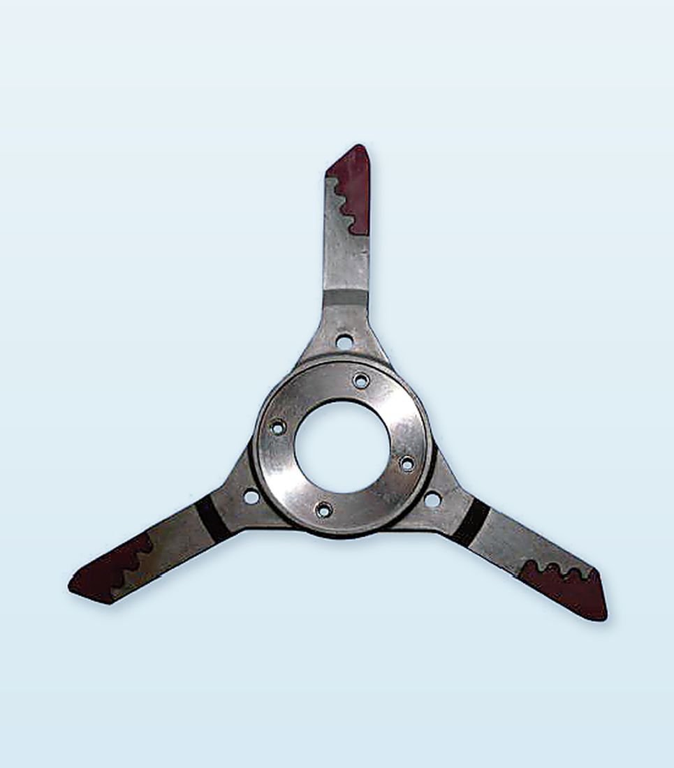
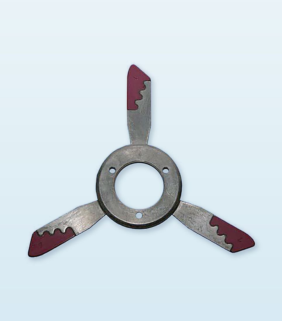
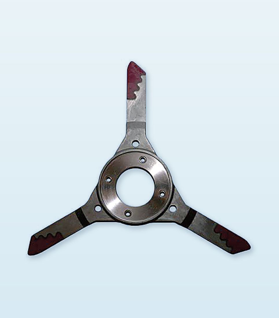
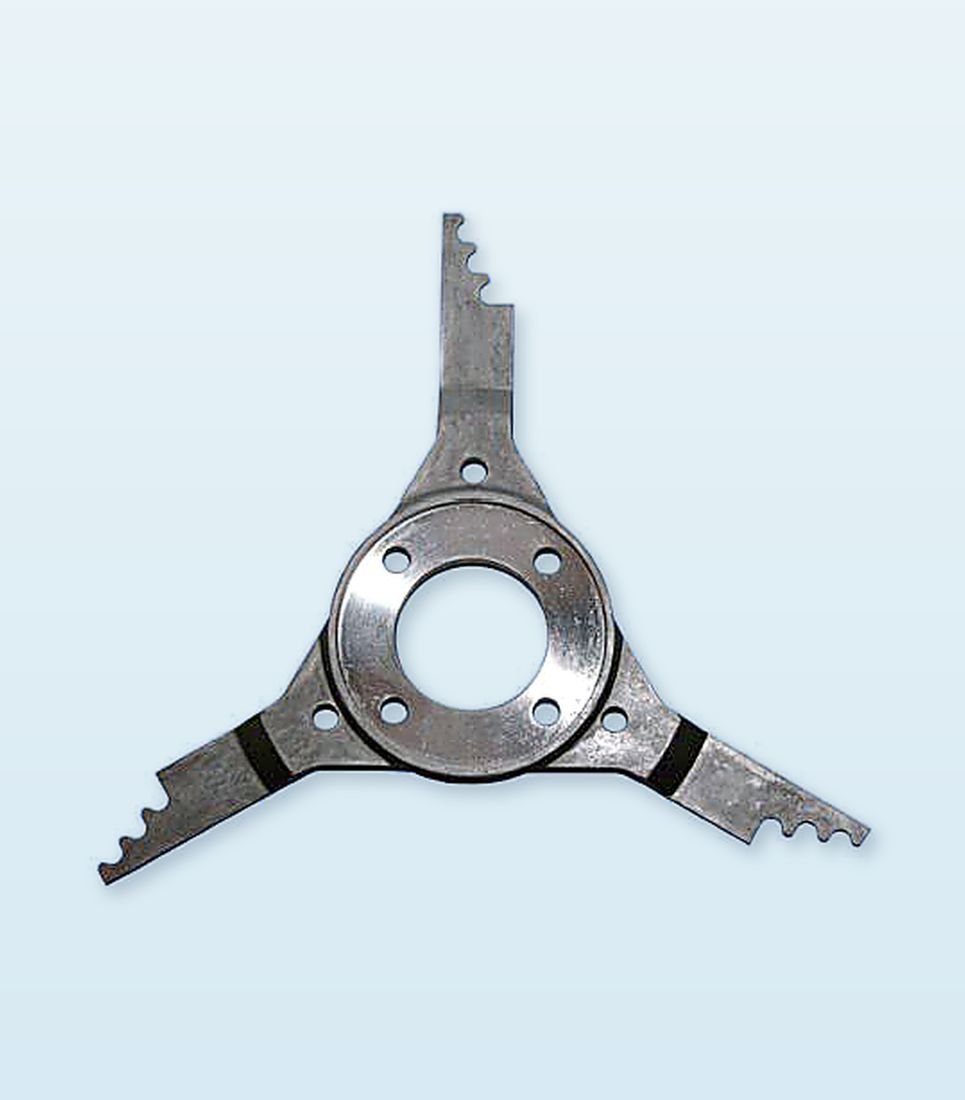
Bi-rotors from our range — rotor shape, mounting format and working-edge configuration vary by machine position, so confirm your exact model against the reference table below.
Confirm direction, mounting geometry and rotor position against your existing part before order.
| JV Model No. | Description |
|---|---|
| JV-1011 | Bi-Rotor Wing Assembly — match rotor position, direction and mounting geometry |
| JV-1012 | Bi-Rotor Wing Assembly — match rotor position, direction and mounting geometry |
| JV-1013 | Bi-Rotor Wing Assembly — match rotor position, direction and mounting geometry |
| JV-1014 | Bi-Rotor Wing Assembly — match rotor position, direction and mounting geometry |
| JV-1015 | Bi-Rotor Wing Assembly — match rotor position, direction and mounting geometry |
| JV-1016 | Bi-Rotor Wing Assembly — match rotor position, direction and mounting geometry |
| JV-1017 | Bi-Rotor Wing Assembly — match rotor position, direction and mounting geometry |
| JV-1018 | Bi-Rotor Wing Assembly — match rotor position, direction and mounting geometry |
| JV-1021 | Bi-Rotor Wing Assembly — match rotor position, direction and mounting geometry |
| JV-1022 | Bi-Rotor Wing Assembly — match rotor position, direction and mounting geometry |
| JV-1023 | Bi-Rotor Wing Assembly — match rotor position, direction and mounting geometry |
| JV-1024 | Bi-Rotor Wing Assembly — match rotor position, direction and mounting geometry |
Send the machine manufacturer and model, the take-up position, and — ideally — a clear photograph of the existing rotor or its reference number. Rotor shape, mounting format and working-edge configuration all vary by machine position, so visual confirmation is the fastest route to a correct match.
Rounded or chipped working edges are the main wear indicator — they reduce the consistency of yarn transfer at each reversal, which typically shows up as irregular package build or occasional yarn slip at the winder.
Yes. Bi-rotors are handed — confirm the direction of rotation along with the mounting geometry and rotor position, since a mirror-image part will not function correctly even if the overall dimensions match.
 Call Us
 WhatsApp
 Enquiry